Home.
June 2026 - Circuit Simulator
Anyone who has played with an Arduino will recall that when you first apply power there is an onboard LED that blinks. That LED is also connected to output PIN 13. This is because new Arduinos invariably come with the “Blink” sketch installed. “Blink” is one of the example sketches that can be subsequently reinstalled if you wish.
So when I discovered a video on Youtube of a free circuit simulator called SimulIDE that included actual “virtual processors”, I started with a virtual Arduino Nano and I installed the blink sketch to see it working. Sure enough, the LED flashed and a virtual logic analyser showed the square wave output.
A video of that sketch running can be seen at this URL (1).

In the left hand panel is a library of components and test equipment – such as signal generators, oscilloscopes and volt meters etc. The middle panel is where you draw your circuit and the right panel is where you can develop your code in C++ , just as you can do in the usual Arduino Integrated Development Environment (IDE).
Of course, if you have already compiled your code in the IDE then you can install the hex code directly into SimulIDE.
Looking further at the provided virtual processors I spotted the very inexpensive ATTiny85 chips. I wondered how well they simulated. So I looked for a suitable project to try and I found one in the form of an electronic CW keyer (2).
The zip file in the above reference contains the hex code you would normally transfer into the real ATTiny85. It works just as well in the simulation.

Above you can see the test circuit. I used a couple of push buttons to simulate the paddle. There are two outputs from the project and one goes to a piezo buzzer for side tone. I monitored that output on a virtual logic analyser, as I did for the other output intended to key your transmitter. There are a couple of virtual voltmeters placed to monitor specific points in the circuit.
There is a video here (3) showing the circuit being powered up and the initial “73” being sent to the buzzer which indicates the keyer is ready. Then the video shows me pressing the “dit” and “dah” buttons - and the output then going to the transmitter.
If the command key is operated the keyer speed can be changed with the “dit” and “dah” push buttons.
If your PC has Linux Mint as an operating system, then SimulIDE is available from the built in Software Manager. Otherwise, you can find the Windows version at this website (4).
I am most impressed with this software which is both useful and completely free. While even more comprehensive simulators such as LTSpice have been around for a while, this is in my view far easier to use and visually more impressive.
Update:
The July 2026 Practical Wireless Magazine had an article written by xx where an ardunio can be used to meter various functions in a radio, for example:
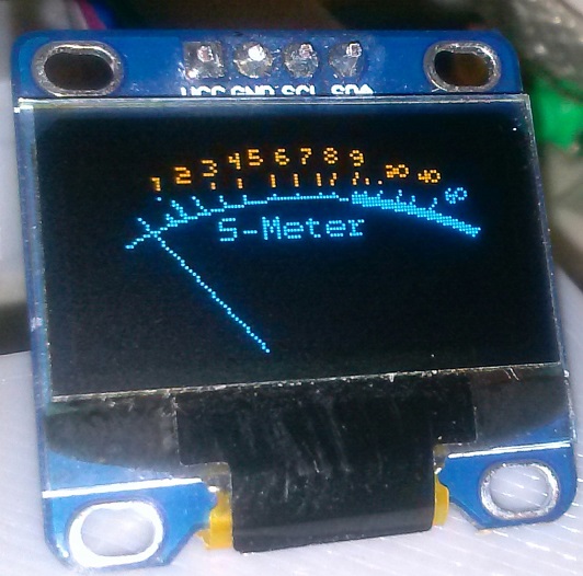
So of course, I had to try simulate that.

The video showing the result can be seen here.
References:
(1) https://youtu.be/5ytEf1EthaQ
(2) https://github.com/donfroula/ATTiny85_CW_Keyer
(3) https://youtu.be/7a8Zf-pUgKM
(4) https://simulide.com